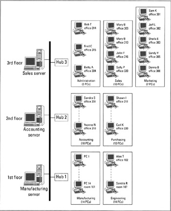
The office building has 3 floors with cubicle and office space for 24 workstations on each floor. Building Small Office Network - Part1 - Network Design - YouTube.
Ccna Cyber Ops Version 1 1 Chapter 5 Network Infrastructure
Never before creation of Network Layout Floor Plans Network Communication Plans Network Topologies Plans and Network Topology Maps was.

Network design 5 floor building. Dear All I would like to design install lan cabling on a 2 Floor Building. All computers in one room are connected to a switch. Often with network diagrams problems arise when you try to attempt to do a logical and physical design in a single diagram.
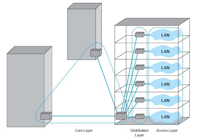
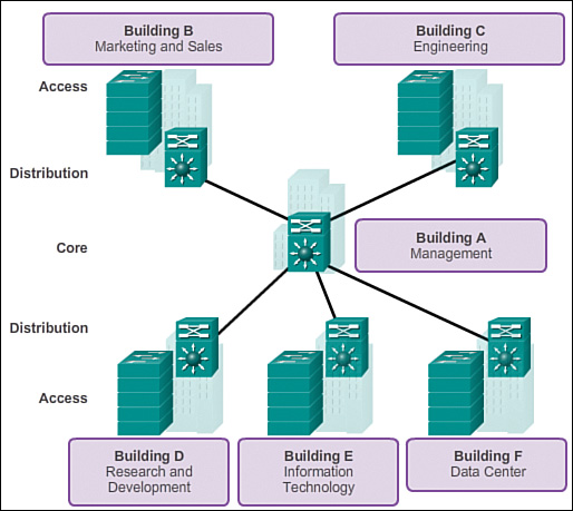
Mamelas asked on 2152012. The campus wired LAN enables communications between devices in a building or group of buildings as well as interconnection to the WAN and Internet edge at the network core. Campus network design concepts include small networks that use a single LAN switch up to very large networks with thousands of connections.
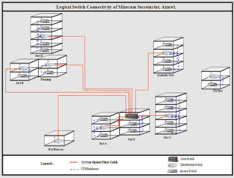
While Category 5 utp systems are limited to 100 meters of total length and require electronics in each TC for high-speed data systems fiber-optic systems do not require the use of electronics in closets on each floor and therefore support a centralized cabling network. The average required throughput on the WAN during work hours 700 am. NetBIOS and RPC are two examples of a layer five protocol.
You can divide and conquer the job and develop the design in layers. 7 Comments 1 Solution 6734 Views Last Modified. At this the network protocol stack software works almost similarly on all physical layers.
Please see the Table 1-Suggestion How to Eliminate Them. Fiber-optic network management therefore is greatly simplified and enables more efficient use of ports on electronic hubs and easy establishment of work-group networks. Each Floor will have computers cisco ip phones network printers network photocopiers access points.
It has one master bedroom with attached bathroom and veranda drawing with attached veranda dining space with kitchen and two common bedrooms with one common bathroom. Network design experts have developed the hierarchical network design model to help you develop a topology in discrete layers. 06 m Walls.
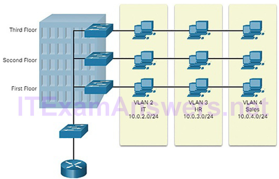
This sample represents in details a Network Floor Plan Layout and shows a plan of an Ethernet computer network that will be constructed using a category 5 cable Cat 5e. Do one diagram with your vlan setup with the departmental separation and another with your hardware setup across the floors. Cat 5e is a twisted pair cable for carrying signals.
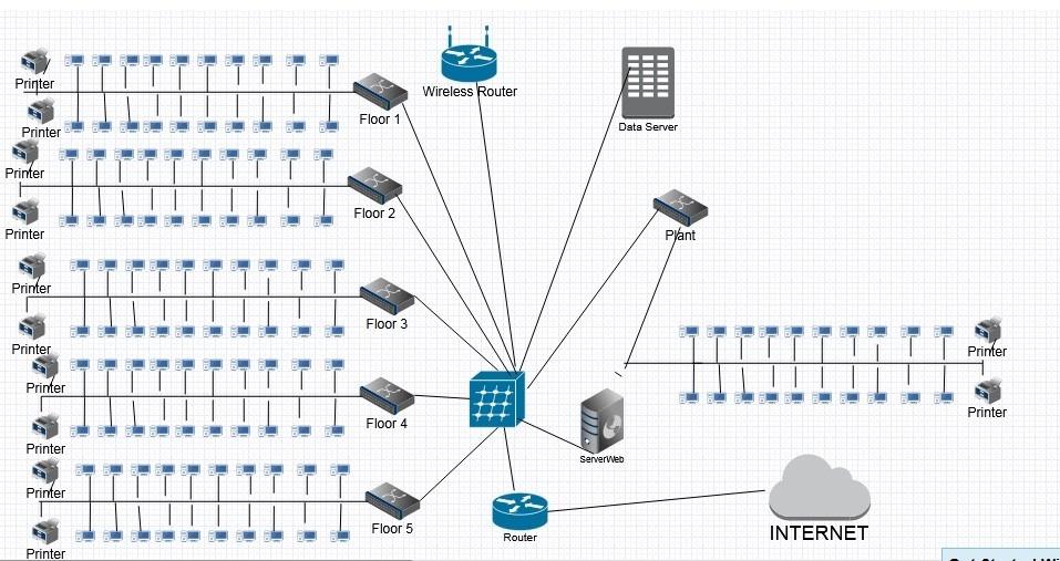
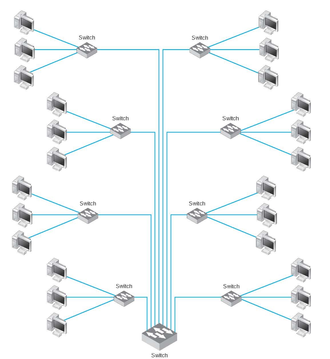
Networking Hardware-Other Switches Hubs Network Management. All switches are connected to one main switch that is located in the IT Department in 5th Floor. It is usually easier to both create and read a network layout where these are two separate diagrams.
Please review the accompanying office diagram for specifics. Each layer can be focused on specific functions allowing you to choose the right systems and features for the layer. Its vary depend on your needs and the size of your project.
Material Properties Concrete All components unless specified in design. Each floor consists of one or more rooms. Network blue prints consists of Single diagram Several diagrams of the network.
Network design and deployment for a small office home office need. Best Network Design for a 2 Floor Building. That switch is connected to 2 routers and to the internet.
Specifically this design provides a network. To be provided at 100 mm below GL. Physical aspects of your network design.
The Server that can access all the networks in the building is located in the IT department in the 5th floor. Master bedroom and the drawing-room dimensions are same of length 14 ft width 13 ft. Additionally on the second floor there is a separate space designated for four file servers which will be used company-wide.
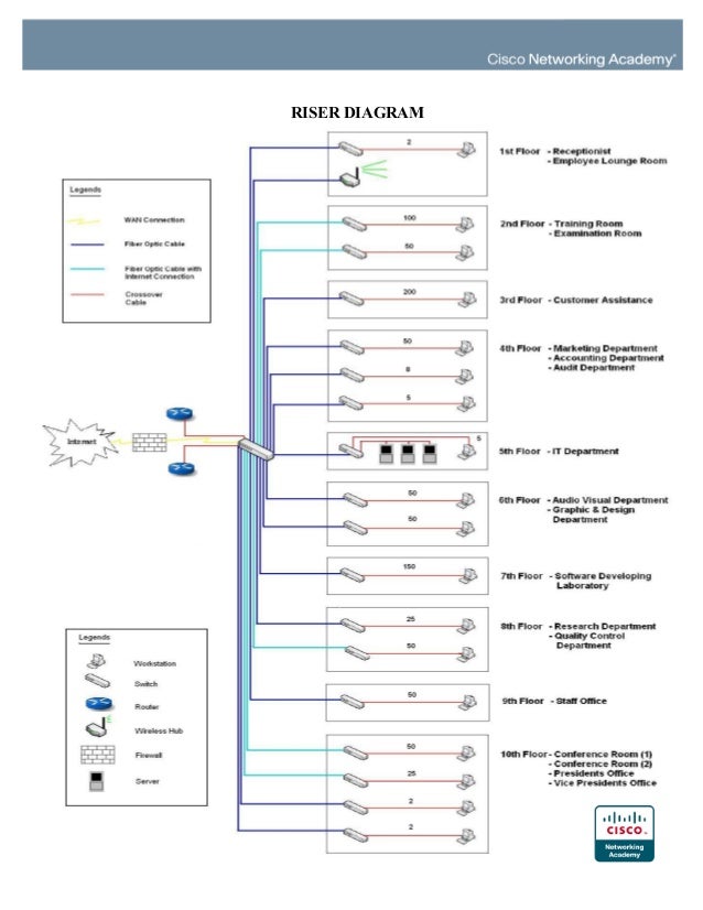
Finally there are two telecommunications closets on each end of each floor for housing network equipment. QUOTE OF THE WHOLE DESIGN The building is a 10-floor building. Find answers to Best network design for a new multi-floor and multiple building from the expert community at Experts Exchange.
M25 grade all Ec 5 000 fck Nmm 2 5 000 fck MNm 2. Will be only 004 mbps. Exam-ples of protocols that operate at this layer are TCP and UDP.
You create a campus network by interconnecting a group of LANs that are spread over a local geographic area. 12 storey building of 315 to 36 m width and 90 m length with a 9 m projection of the upper 4 floors Pairs of cellular beams were placed either side of the 4 inclined tubular columns. The cellular beams were designed as continuous over a span of 15 m in order to reduce their depth The floor-floor zone is a minimum of 365 m and.
5 upper floors. PHYSICAL DESIGNIn this section the physical topology demonstrates the direction of the physical design implementation and illustrates the major points of the network upgrade which includes the devices locations and cable installationIn the main floor of the building the mainframe and the five servers are in place. Network blueprints A component plan Vendor Vendor equipment Service provider selection Metrics for measuring design success.
4 Transport The Transport Layer provides a method of reaching a particular service on a given network node. Network Layout Floor Plans solution extends ConceptDraw DIAGRAM software functionality with powerful tools for quick and efficient documentation the network equipment and displaying its location on the professionally designed Network Layout Floor Plans. It is convenient to use callouts to convey the additional information for a viewer of this plan and it is a.
The average required throughput on any LAN during work hours 700 am. It presented the steps or phases of a structured network design and demonstrated a practical implementation of the steps using a real-life case study. Unit-B stays 50 present floor area on the ground floor.
The data indicate the following network design parameters. The design was first simulated using Cisco Packet Tracer software and WireShark protocol analyser. Some protocols at the transport layer.
34 m Floors. Will be only about 02 mbps. For example in Figure 5-1 high-speed WAN routers can carry.
5 Session The Session Layer manages the logical communica-tions session between applications. Design products The key products of a network design are. 230 mm thick brick masonry walls only at periphery.
3 Floor Building Network Design
Department Of Information Communication Technology
3 Floor Building Network Design
Backbone Network Architectures Data Communications And Networking Part 1
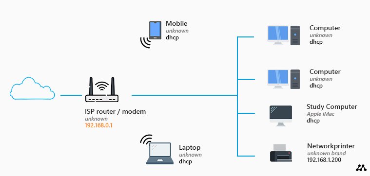
Home Network Diagram All Network Layouts Explained
Floor Plan Network Design


1601 S Jefferson Chicago Building Rendering Commercial Building Plans Apartment Architecture
Backbone Network Architectures Data Communications And Networking Part 1

4 Vlans And Trunking Packet Guide To Routing And Switching Book
3 Floor Building Network Design
3 Floor Building Network Design

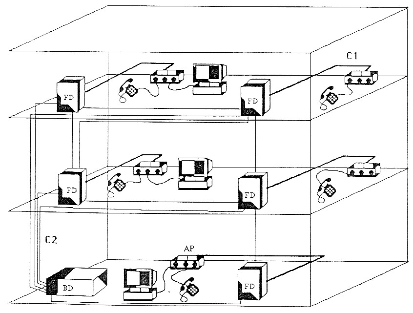
In Building Network Architecture With Three Floors And A Basement Download Scientific Diagram

Weblan Designer Wired Lan Scenarios
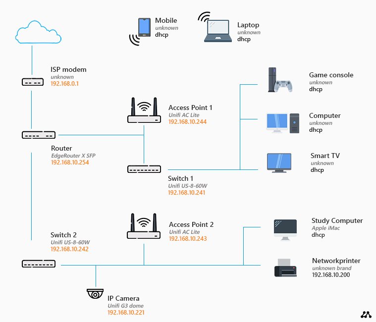
Home Network Diagram All Network Layouts Explained
Pin Oleh Mukamu Jelek Di Project Wijk Van De Toekomst

Conceptdraw Samples Computer And Networks Network Layout Floor Plan Restaurant Floor Plan Floor Plans Floor Plans Online
12 Network Building Design Images Office Building Layout Plan Network Analysis And Small Office Network Design Newdesignfile Com
Network Design Proposal For Small Office Ppt

In Building Network Architecture With Three Floors And A Basement Download Scientific Diagram
Komentar
Posting Komentar